
This is part 3 of a series of articles on the 555 timer. Part 1聽goes into more detail about the pins聽and how the chip聽functions, so you might want to start there if you haven’t read it already:聽 555 Timer Basics – Monostable Mode.

Astable Mode of the 555 Timer
The astable mode is what most people think of when it comes to the聽 555 timer. Many times when you see a project with flashing LEDs, it’s a聽555 timer at work. But it has a lot of other interesting applications too. For example, it can also generate frequencies to聽produce sound when the output is connected to a speaker. It can even be used聽as a simple analog to digital converter (ADC).
In astable mode, the 555 timer acts as an oscillator that generates a square wave. The聽frequency of the wave can be adjusted by changing聽the values of two resistors and a聽capacitor connected to the chip. The formulas below will tell you the length of the output’s on and off cycles with different resistors and capacitors:

With this equation, you can see that increasing the values of either C1 or R2 will聽increase both the time the output stays on and the time it stays off. Increasing the value of R1 will only lengthen the time the output stays聽on.
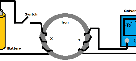
How Astable Mode Works
- Pin 2 – Trigger: Turns on the output when the聽voltage supplied to it drops below 1/3 of Vcc
- Pin 6 – Threshold:聽Turns off the output when the voltage supplied to it reaches above 2/3 Vcc.
- Pin 7 – Discharge: When the output voltage is low, it discharges C1聽to ground.
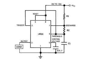
In astable mode, the output cycles on and off continuously. In the schematic above, notice that the threshold pin and the trigger pin are connected to C1. This makes the voltage the same聽at the trigger pin, threshold pin, and C1.
At the beginning of an on/off聽cycle, the voltage is low at聽C1, the trigger pin, and the threshold pin. Whenever the trigger pin voltage is聽low, the output is on, and the discharge pin is off. Since the discharge pin is off, current can flow through resistors R1 and R2, charging聽capacitor C1.
Once C1 charges to 2/3 Vcc, the output is switched off by the threshold pin. When the output goes off, the discharge pin switches on. This allows the charge accumulated on capacitor C1 to drain to ground.
Once the voltage across C1 drops to聽1/3 Vcc, the trigger pin turns off the聽discharge pin, so C1 can start charging again.
A Blinking LED聽Circuit
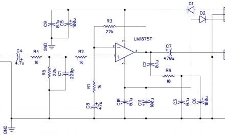
To observe the 555 timer in astable mode, let’s build聽a circuit that聽uses the 555 timer’s oscillating output to make an LED flash on and off:
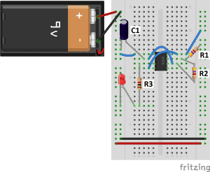
- R1: 4.7K Ohm resistor
- R2: 4.7K Ohm resistor
- R3: 1K Ohm resistor
- C1: 100 渭F capacitor
The values of R1, R2, and C1 affect the speed of the blinking. Larger values will make聽the LED blink slower, while smaller values will make the LED blink faster. Resistor R3 is just there to limit the current to the LED so it doesn’t burn out. If you want to set the blinking to a certain speed, you can use the formula at the beginning of this article to calculate the resistance or capacitance you need.
Blinking聽LED Controlled by a Potentiometer
An easy way to observe the effect of resistance on the blinking speed聽is to use聽a 10K Ohm potentiometer聽for R2:
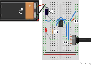
- R1: 4.7K Ohm resistor
- R2: 10K Ohm聽potentiometer
- R3: 1K Ohm resistor
- C1: 100 渭F capacitor
Adjusting the potentiometer will change the rate of the LED flashing.
Blinking聽LED Controlled by a Photoresistor
Instead of using a potentiometer to control the blinking聽rate, try connecting a photoresistor:
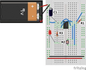
- R1: 4.7K Ohm resistor
- R2:聽Photoresistor
- R3: 1K Ohm resistor
- C1: 100 渭F capacitor
The resistance of a photoresistor decreases as more light shines on it, so the LED will flash more quickly when exposed to more light.
If you want to learn more about the 555 timer, the book聽 Timer, Op Amp, and Optoelectronic Circuits and Projects Book Vol. 1 By Forrest Mims聽is a great resource to have on your bench. The book has lots of information about the 555 timer, OpAmps, and other IC’s too.
You can watch how聽each of the circuits in this tutorial work in this video:
If you have any questions or are having trouble with this project, please leave a comment below and I’ll try to answer it as soon as possible… And don’t forget to subscribe to keep up to date on our latest articles!


First I want to thank u so much….. and I want the led to be off longer than it’s on….
For example… if the led is on for 10 seconds….. then off for 60 seconds…
Plz can u help me
Did you read this part?
t(on)=(0.69)(R1+R2)(C1) in seconds
t(off)=(0.69)(R2)(C1) in seconds
no
it is not possible to do that directly on a 555 timer (ON time >= OFF always) . but you can design on time = 60 secs and off time as 10 secs and use a transistor at the output configured to invert then it will work a treat.
Absolutely you turn the LED off longer then it is on. Hook your LED to pins 3 and 8. This will change the formula to:
t(OFF)=(0.69)(R1+R2)(C1) in seconds
t(ON)=(0.69)(R2)(C1) in seconds
It’s called sinking.
For off time change R1
For on time change R2 and/or C1.
Hope this helps someone
thank you
555 timer
howto make the same circuit for a servo tester?
Can I put more then one led ?
Guess you could put multiple in parallel, each with their own resistor (or even with a common one calculated). To avoid burning LEDs try 123D circuits free online from Autodesk, shows you when LED burns
May I know how to blink the led (on) for 10 second and (off) for 60 second as the first question mentioned?
Hi Sovatna, this brings up an interesting point – the time off actually can’t be longer than the time on. Looking at the equations for time on and off:
Ton = 0.69 x C1 x (R1 + R2)
Toff = 0.69 x C1 x R2
We can see that the only way to get a Ton smaller than Toff (with C1 and R2 constant) is with a negative R1. Which of course doesn’t exist. Thanks for the question!
isn’t there some way to negate the logic at the led side?
If you short circuit R2 with a diode going one way ( away from capacitor) it will skip R2 while discharging.
This setup will allow you to increase Time on, or time off, independently from each other as the power will only flow one direction through that diode.
Pls, i want to make :
On = (0.1) Off & = (0.05) Off
Frequency = 25 Hz & 50 Hz & 100 Hz & 200 Hz & 500 Hz & 1K Hz & 2k Hz & 4K Hz & 5K Hz & 10K Hz
( 10 steps )
meaning (TH) and (TL)???
TH means time the signal stays high
TL means time the signal stays low
What will happen if I change the power source from 9V to 5V, will it work fine?
yes definitely
Great resource thank you very much. Could you please do a circuit that has a longer off time than on. Any example of this would be great and I could then work out the values I need from there. My project requires time low for 10 minutes and time high for 30 seconds. I have ready the other comments who ask for this and understand that it may not be possible with one 555 timer, but can it be done with a 556 or 2 555’s? or by inverting the load? I’m still a novice and any help would be appreciated. Cheers
Alright so guys if you invert the led so it goes from pin 3 to positive and crank R1 you will get a longer off time than on. And it will still trigger itself.
Awsome explenation really
Does this circuit work? I did exactly the same but mine stays on for one second and doesnt turn back on.
does it do that also when you keep the trigger say button pressed? because thats exactly what i麓m looking for..!
But the wit 3Volt.
Why does the schematic use a second capacitor for output 5, but a resistance in the video?
Is it possible to offset a very much larger or smaller C1 value with different R1/R2 values, or should C1 be always around 0,1 mF ? Ive seend examples using C1 values ranging from 0,01 mF to 100 mF.
In my circuit control volt 0- 10 v on pin no 4 (reset pin ) the output is controling. Please explain
wish list: pulses to control a stepper motor controller . 5V sq wave Depoy motor position feedback: eg flag operation at limit with micro switch to STOP pulses So stop stepper motor.
then push button to restart : is there a pin to stop sq wave output Wait for input to restart ?
No thanks Arduinio etc programming Dedicated cct be best.
amateur learning Phil
In the Blinking LED Circuit with the Potentiometer part, is it possible to only have 1 1K resistor, 1 Potentiometer, 1 10 uF capacitor, 1 100 uF capacitor?
If so, can someone please send a picture of a breadboard (not schematic) diagram of it.
Something’s not right. The LED only blinked once not continuously using a potentiometer. I followed exactly the diagram except that I replaced R1 into a direct connection. I need help to look exactly the problem.
C1: 100 渭F capacitor, what is the voltage or this capacitor.. pls answer..
Thanks a lot for the blinking LED circuit.
I tried to make the trimpot controlled circuit, the thrimpot was acting like a light dimmer, I don鈥檛 know why…
C1=22渭f R1=10k惟 Trimpot=10k惟 R3=10k惟.
I know, I made a typo…
Can we make a system of different output time. For example, a system which on for 2 min. then off for 10 min. Agin on for 2 min..
If we can make then how? Please, send circuit for this.
I want to blink two led’s at the same time with the timing being for both to blink once every second using a 9V battery and 555 timer. What is needed to do this and how do I proceed?
OMG THANK YOU! Here I was convinced I was an imbecile for not being able to get blinks after 2 hours, THANK YOU!!!!!
Can be used astable circuit for a power inverter switch pulse?
How to connect the variabel resistor it have a three pin , please guide me, i have tried but it not worth it :'(