
Quote of the Day
It is impossible for a man to learn what he thinks he already knows.
— Epictetus, Discourses, Book II Ch.1. This quote caused my career to flash before my eyes.
Introduction

Figure 1: 555 Timer Circuit Causing Analysis Issues.
I received a request for design formulas that can be used to estimate the frequency (f) and duty cycle (DC) generated by the 555 timer-based, Pulse Width Modulator (PWM) circuit shown in Figure 1. The presence of diodes in the charge and discharge paths are the main cause of the confusion.
In this post, I will provide: (1) analytic expressions for both f and DC, (2) a detailed derivation of these expressions using Mathcad, (3) an LTspice simulation illustrating how potentiometer resistance affects f and DC, and (4) an error analysis showing the quality of the relationship between the design formulas and the simulation.
As I have mentioned in other posts, I am busy building a cabin and large workshop in northern Minnesota. This means my post will include limited explanatory information because my time is limited.
For those who are interested in my source, my files are here.
Background
Equation 1 can be used to compute oscillation frequency (f) of the circuit of Figure 1 (component locations are defined in Figure 3).
| Eq. 1 | 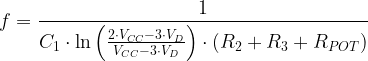 |
where
- f is the oscillation frequency.
- RPOT represents the total potentiometer resistance.
- R2, R3, and C1 are passive component values defined in Figure 3.
- VD is the diode voltage.
- VCC is the supply voltage.
Equation 2 allows you to compute the duty cycle (DC) as a function of resistance.
| Eq. 2 | 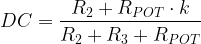 |
where
- k represents the potentiometer's normalized wiper position, i.e. k ranges from 0 to 1, inclusive.
Notice how Equations 1 and 2 allow you to set the frequency and DC independently. First, set your duty cycle by selecting your resistors, then set your frequency by picking the corresponding capacitor.
Analysis
Formula Derivation
Figure 2 shows my derivation of Equations 1 and 2 using Mathcad 15. There are a couple of things to notice about the formulas:
- The forward voltage of the diode only affects the oscillation frequency.
- The duty cycle is a function of the resistances and the potentiometer wiper position.

Figure 2: Derivation of the PWM Formulas.
Simulation Work
I wanted to simulate the circuit in a way that did not require the use of special libraries – like the potentiometer library or a cleaner 555 symbol. Instead, I decided to use two resistors with values that vary in the same manner as the resistance in a potentiometer. Using this approach, I could then created a "wiper" that varied with time, i.e. 
I also used the standard 555 symbol, even though I do not like the way this symbol connects to other parts on a schematic (Figure 3). Yes – I am a bit of a schematic artist.

Figure 3: LTspice Implementation of the 555 PWM Circuit.
Figure 4 shows the simulation result. As you can see, duty cycle varies as the "wiper" position is changed, i.e. time advances. As expected from Equation 1, the oscillation frequency holds constant as the wiper position is varied.

Figure 4: Output Voltage Simulation For the Circuit of Figure 2. I am only showing part of the simulation because the fine detail is lost at larger scale.
Error Analysis
Figure 5 shows ten data points for which I computed the frequency (Equation 1) and duty cycle (Equation 2) using Mathcad and LTSpice. The agreement is reasonable.

Figure 5: Comparison of Equations to Simulation.
Conclusion
This post derived a pair of formulas that can be used to design a simple, potentiometer-controlled, PWM circuit. The derivation showed good agreement with a Spice simulation of the same circuit.
why frequency changes? your f formula does show 位会员